ISU Audio and Arduino Club
DC supply build instructions
- Below are step-by-step instructions for building the DC-Supply project. The PCB is fairly simple and should be easy to solder. However, there are a couple of tedious parts — soldering in all the feedback resistors and soldering the 2-pin headers for each of the resistors. Take your time and work carefully to minimize goof-ups.
- Note that if you know that you will use only a couple of output values or you want to use only the continuously varying option, then it is not necessary to solder in all of the resistors and headers. You can just the one or two that you want. The board could then be completed much faster.
- The order of assembly given below is a suggestion — there is nothing wrong with soldering the parts in a different order.
- The usual tools are required: solder and soldering iron, needle-nosed pliers for manipulating parts and pulling leads through holes, and wire cutters for trimming leads after soldering. Helpful but not essential would be a vise for holding the boards and a magnifying glass and light for viewing small print.
- To view the photos at higher resolution, open the images in a new tab or window.
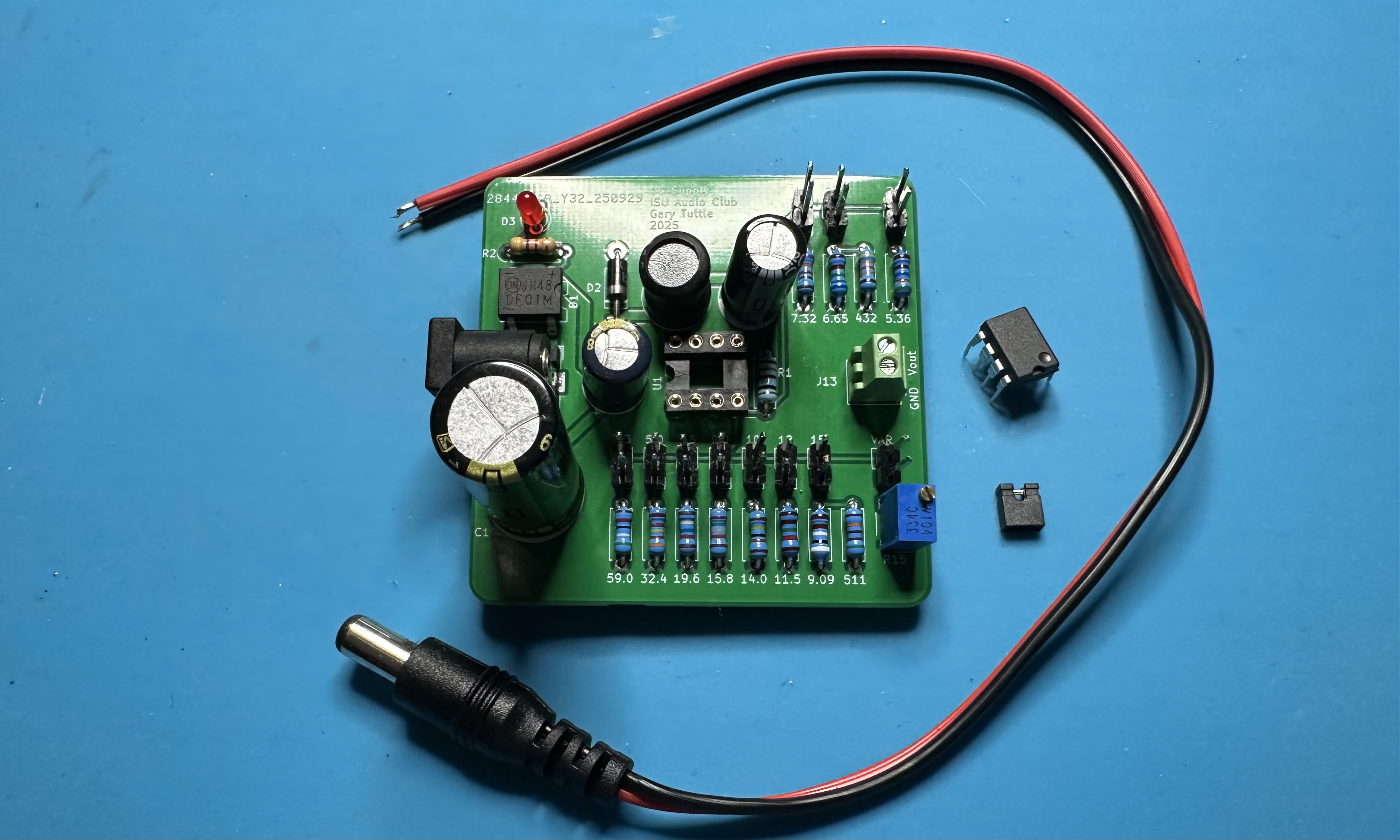
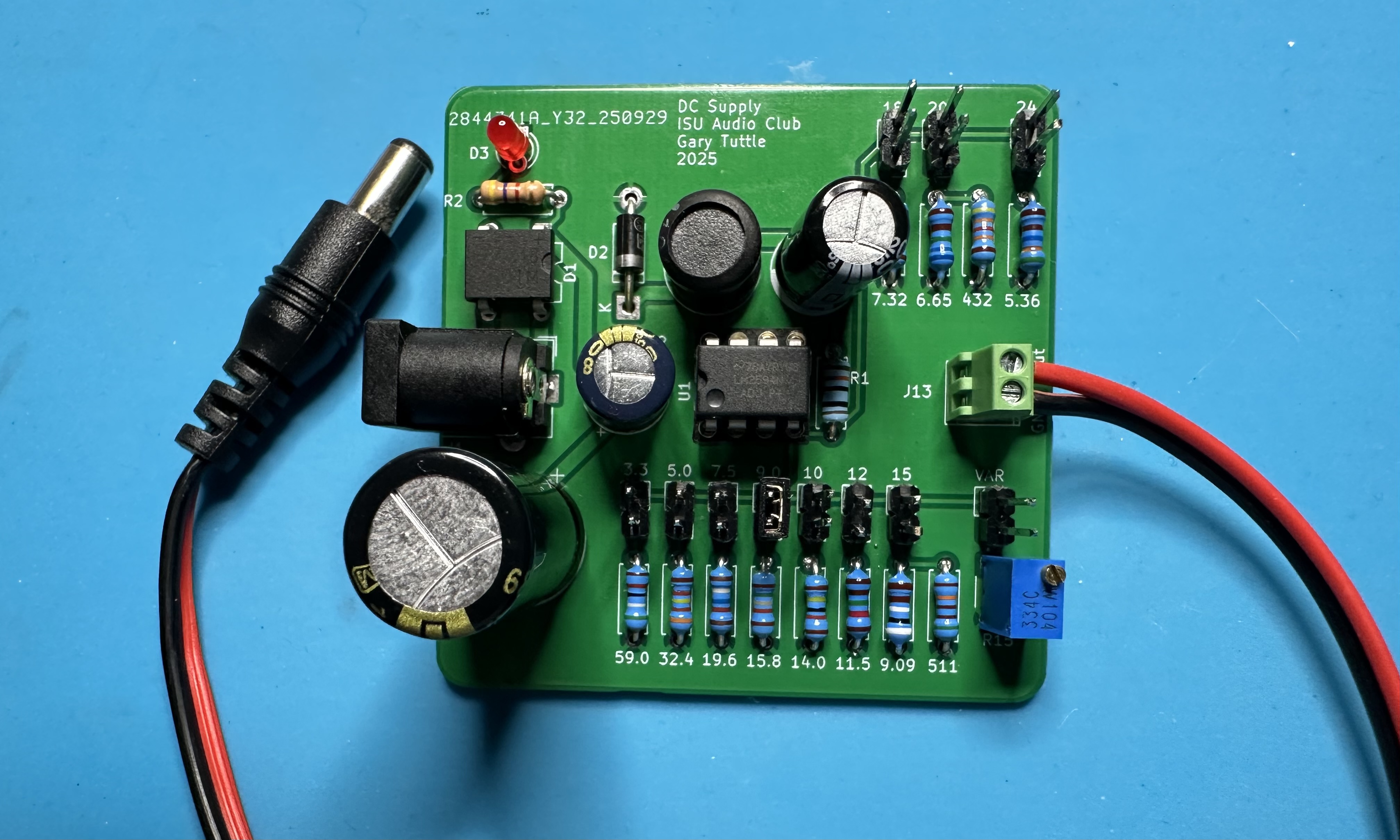
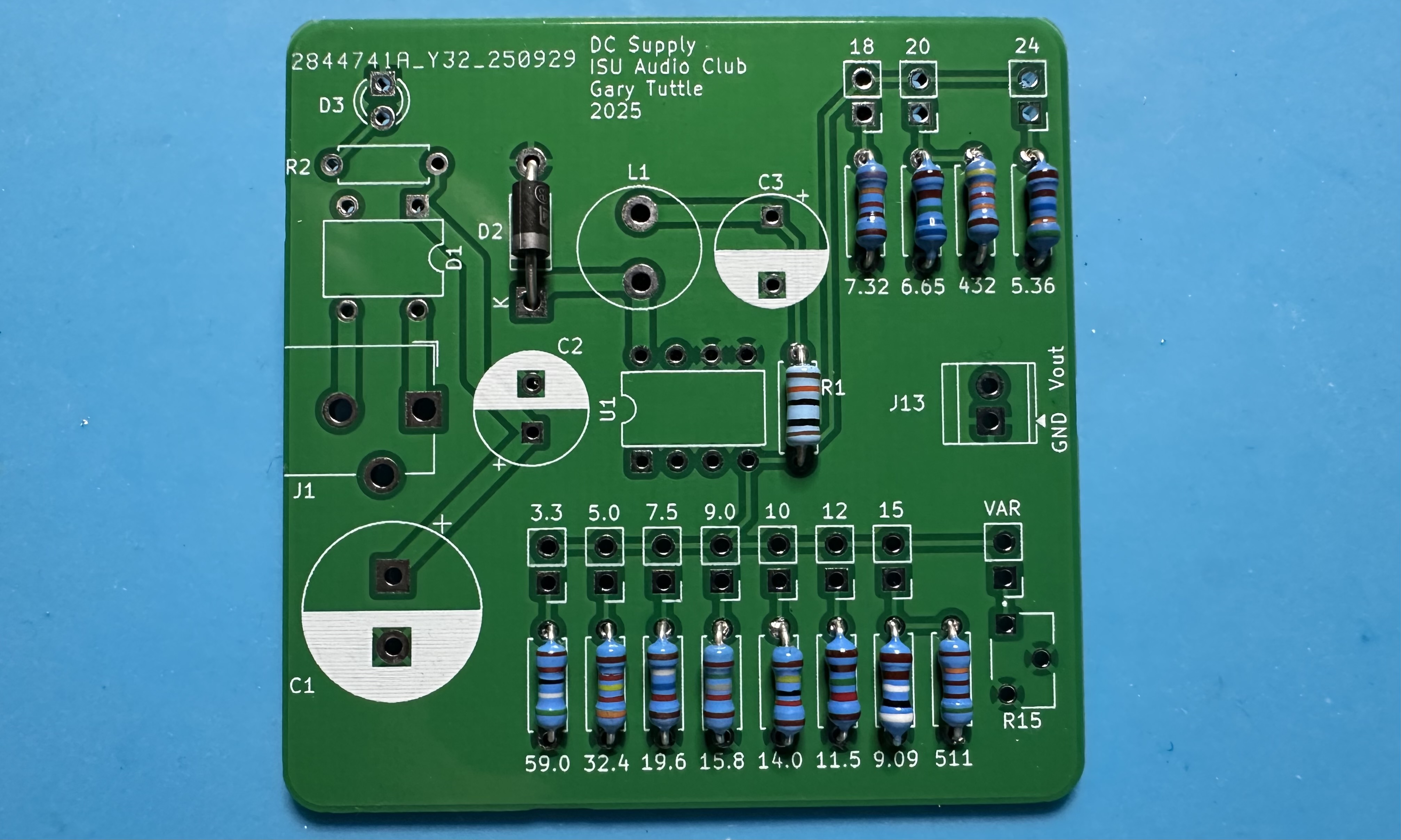
- Assemble the parts. (See the BoM for the complete list.)
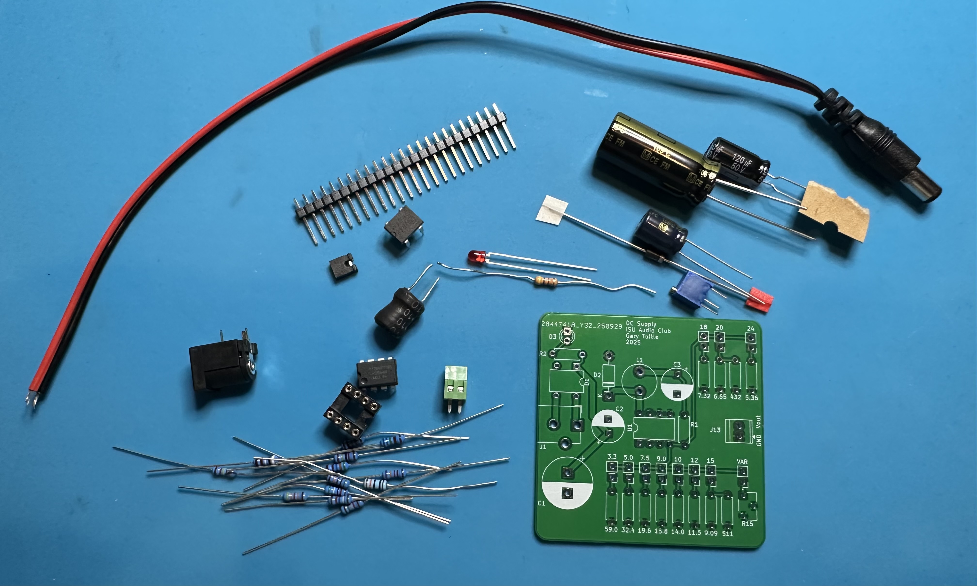
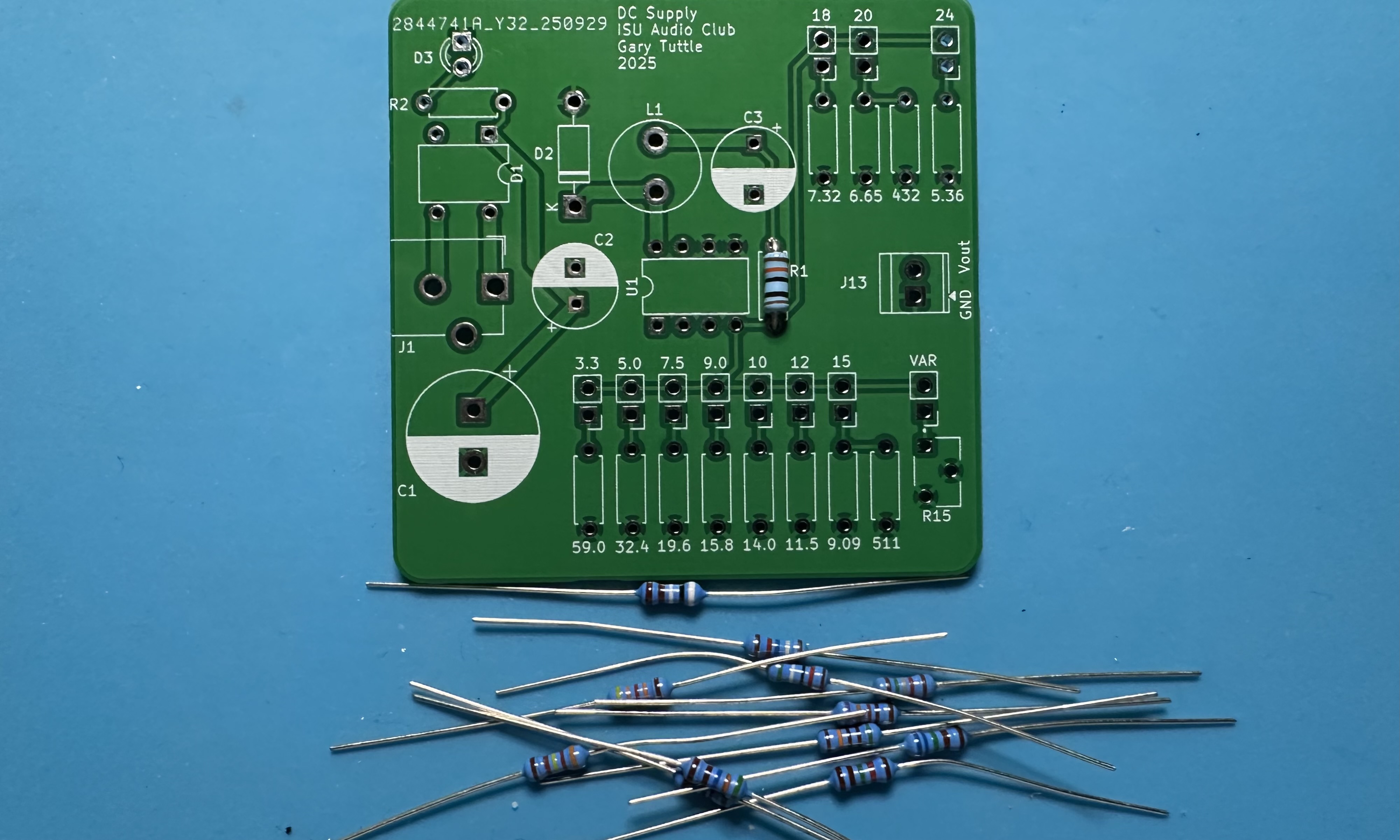
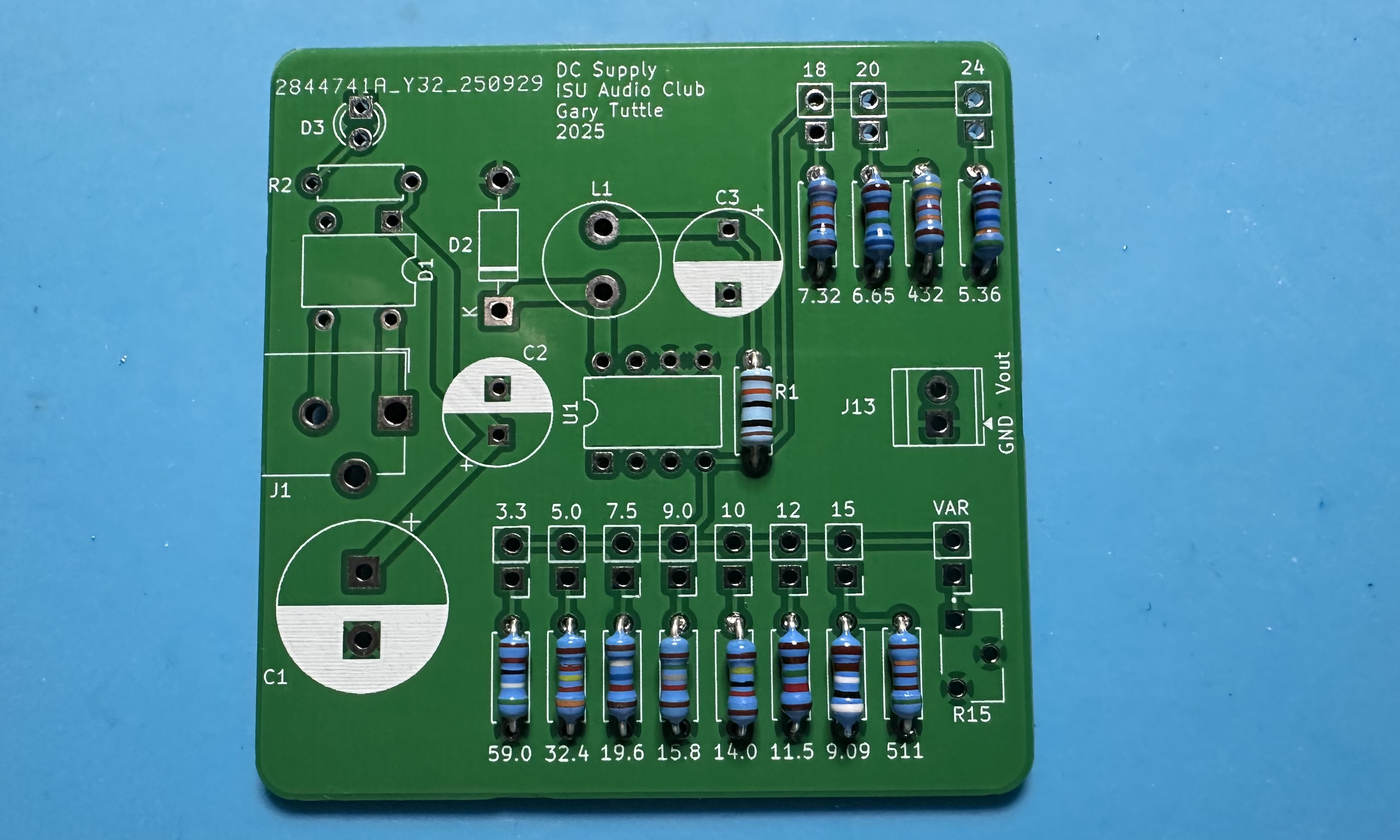
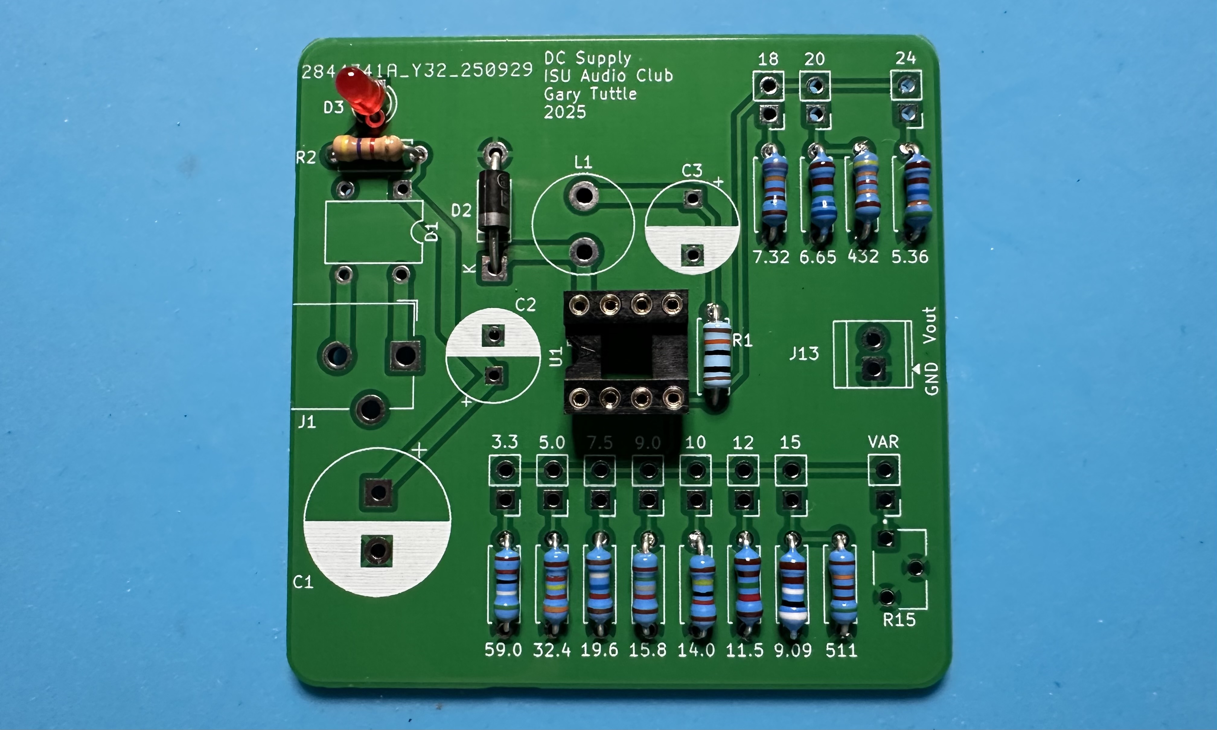
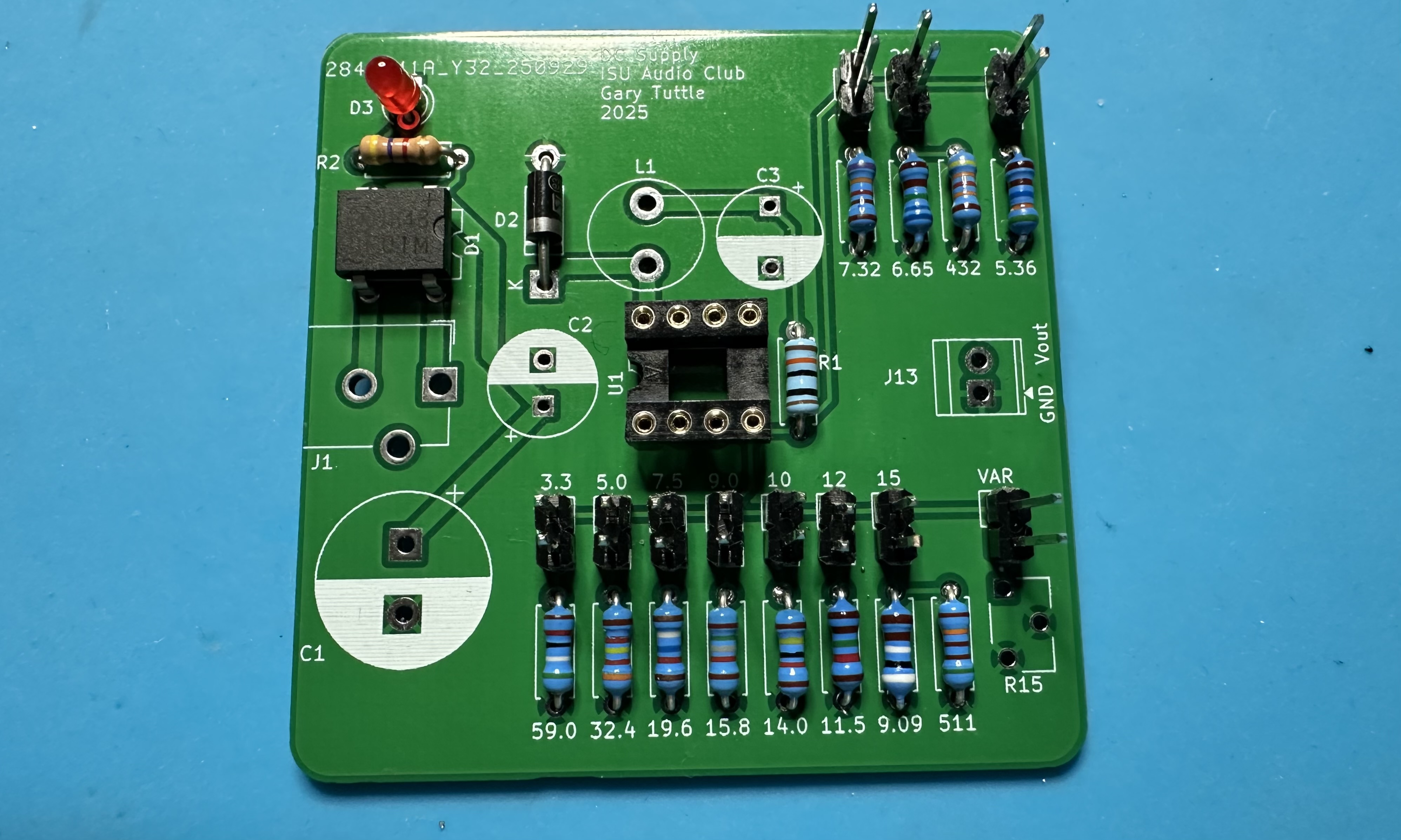
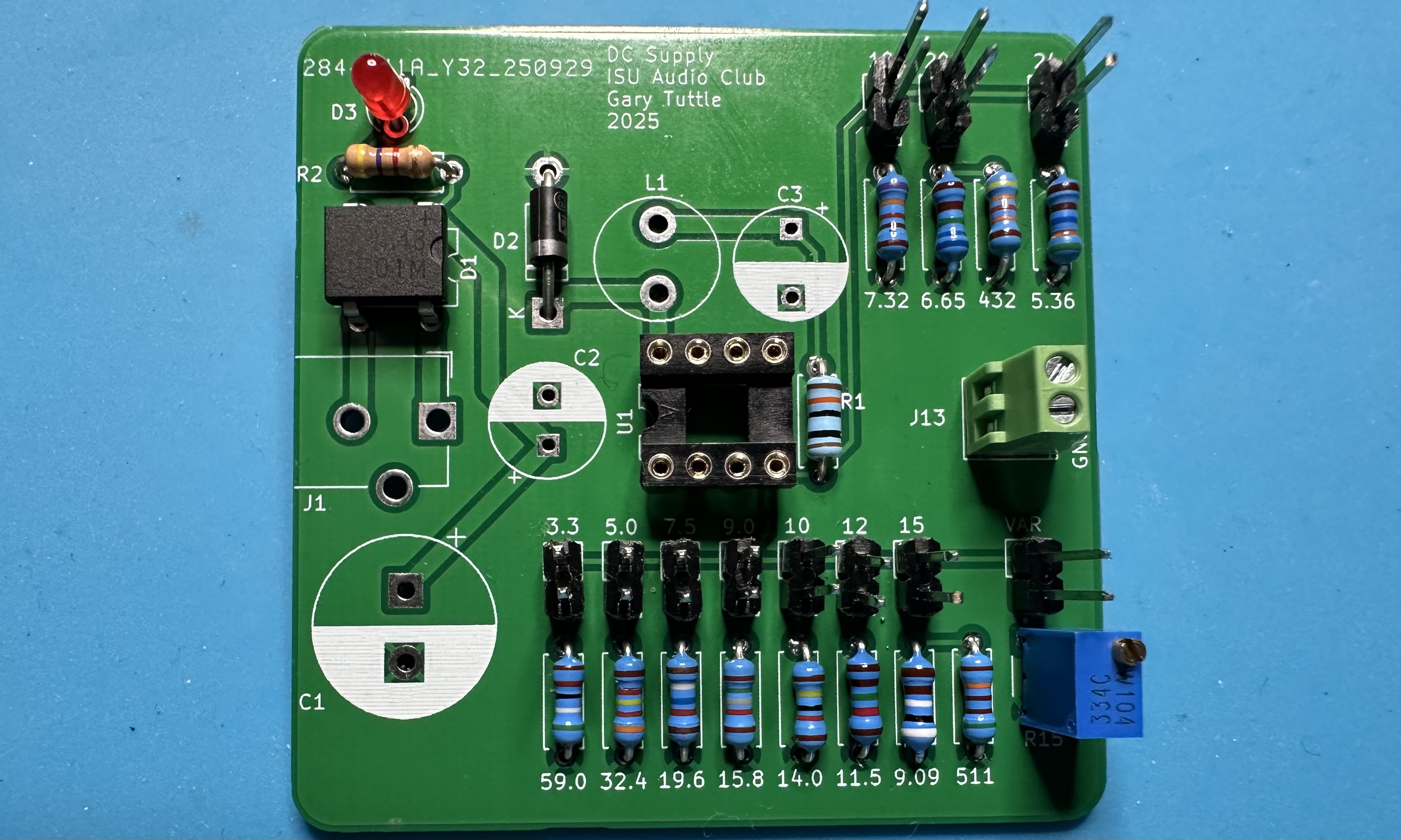
- As usual, we start small and work our way to the bigger parts. There are many resistors used for the various feedback path options — let's start with those. First, install the 100-kΩ resistor.
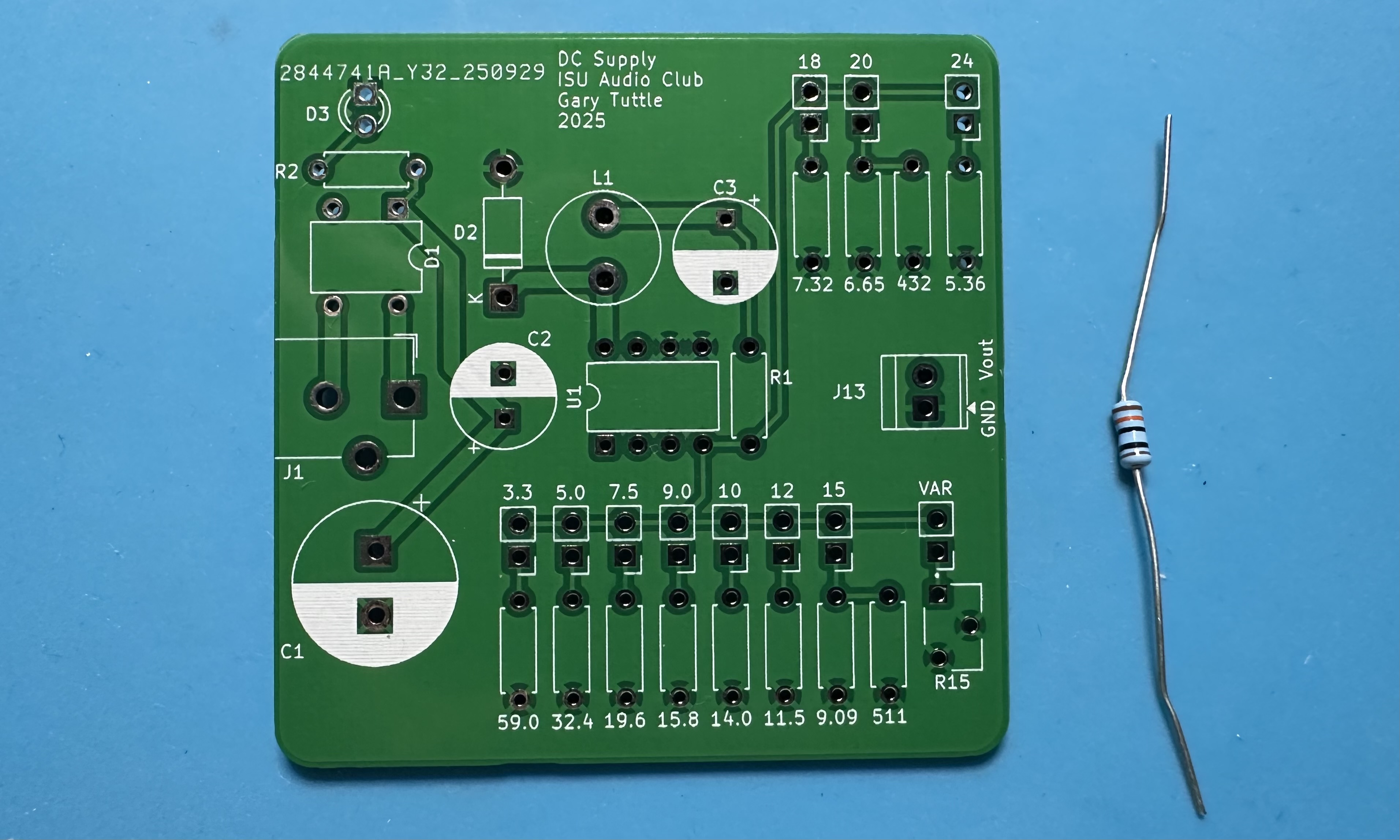
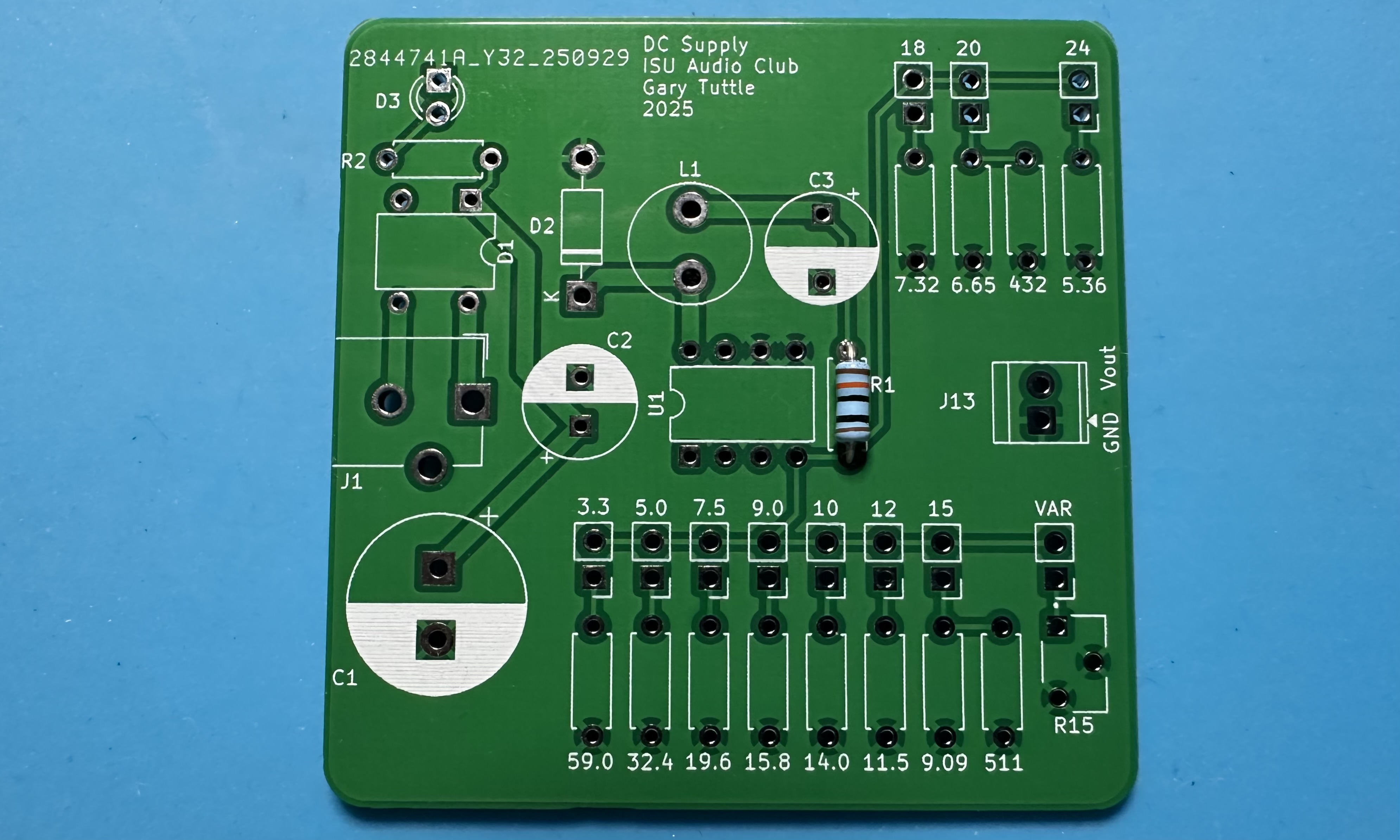
- Now, do the tedious work of putting in all of the other 1% resistors. These have unusual values (unusual to us, anyway), so read the color codes carefully. Better yet, measure each resistor before soldering it in place. The board is labeled with the expected values for all resistors. Take your time and make sure that each resistor is in its proper place.
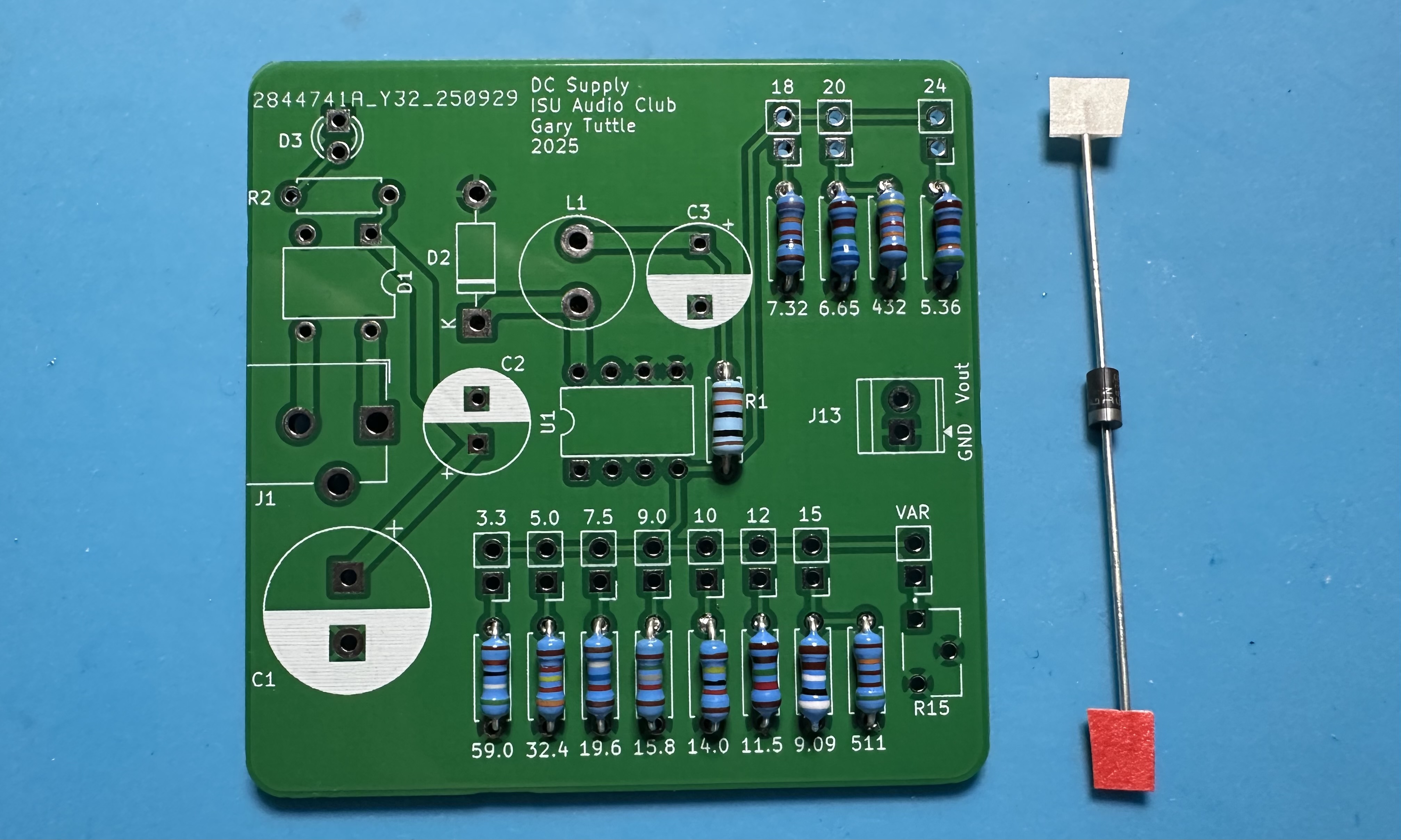
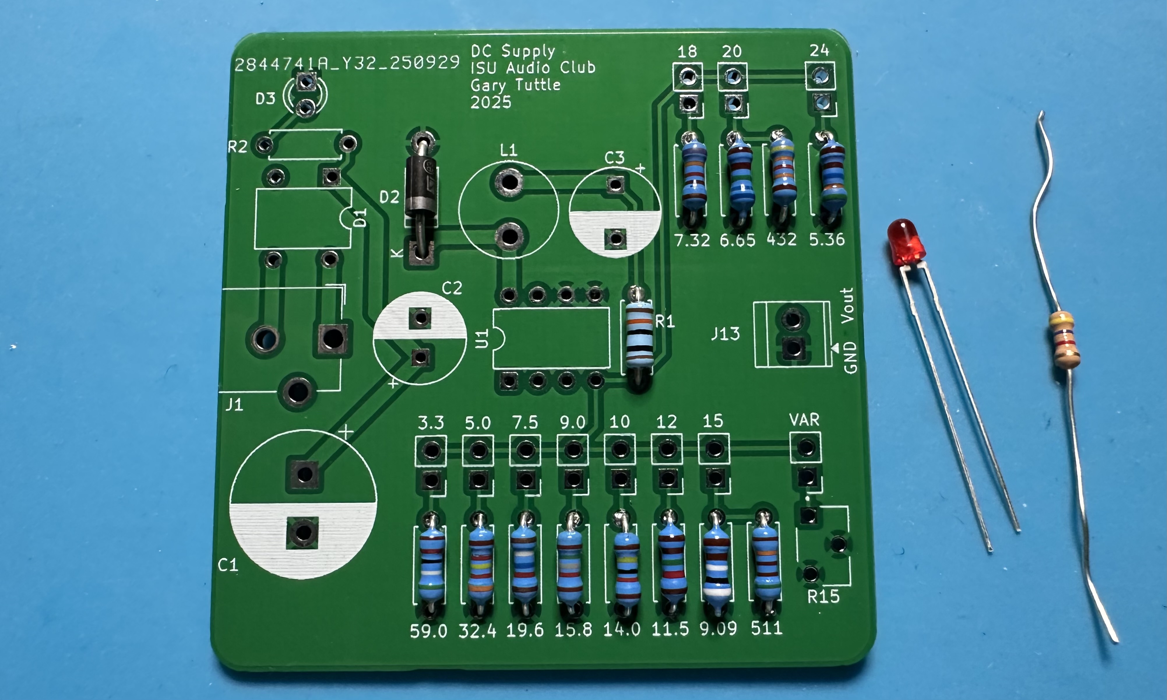
- Next, the Schottky diode for the switching regulator, labeled D2. Diodes are directional, so it is important to solder it in with the correct orientation. There is a stripe on the diode that corresponds to the cathode ("pointy end") of the diode. The stripe on the diode should match the stripe on the footprint.
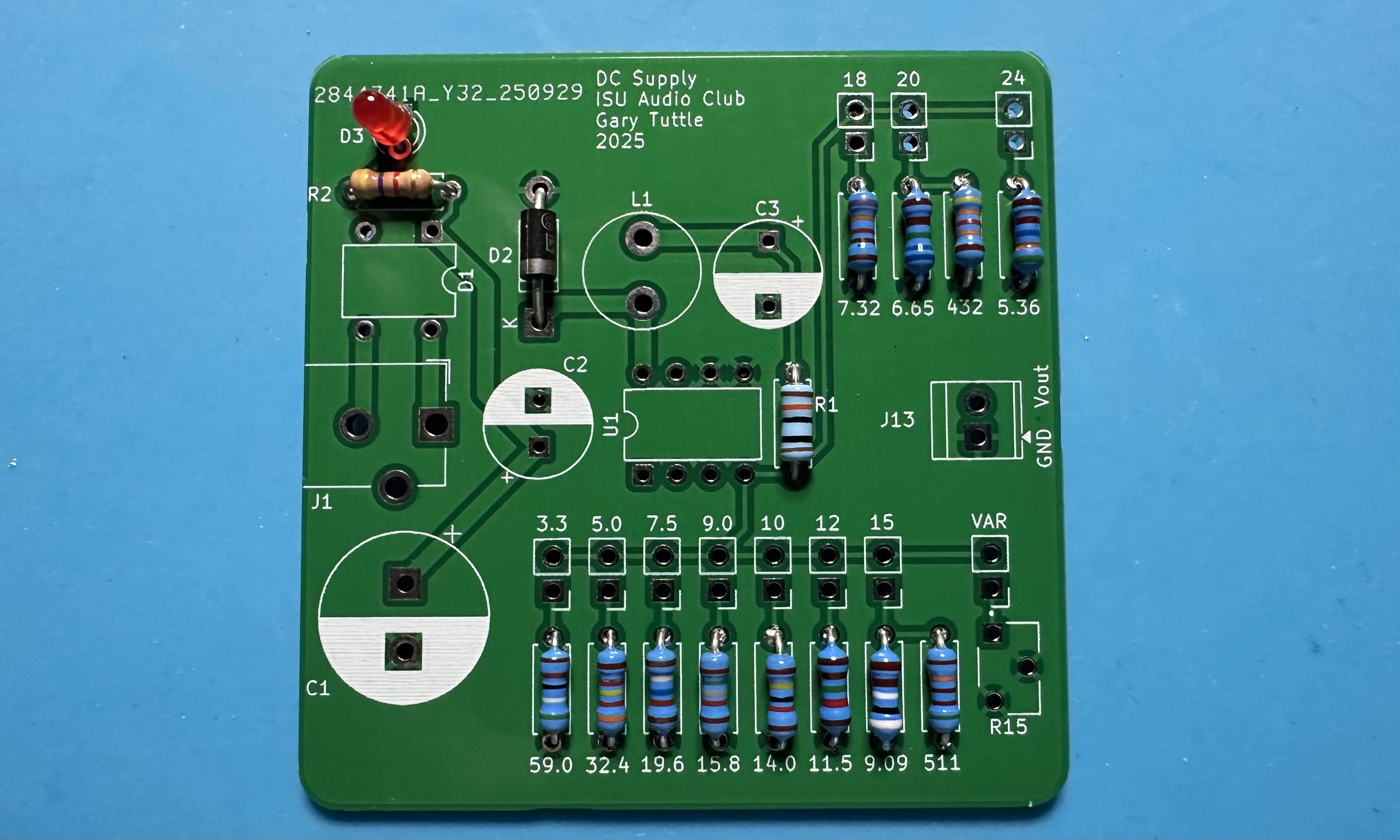
- Next up, add the "power on" LED, D3, and its 4.7-kΩ limiting resistor (yellow, purple, red) in R2. As with the Schottky diode, direction is important for the LED. The longer lead is the anode (positive) and goes in the circular through hole. The shorter lead is the cathode (negative), and it goes in the hole with the square outline — connected to ground
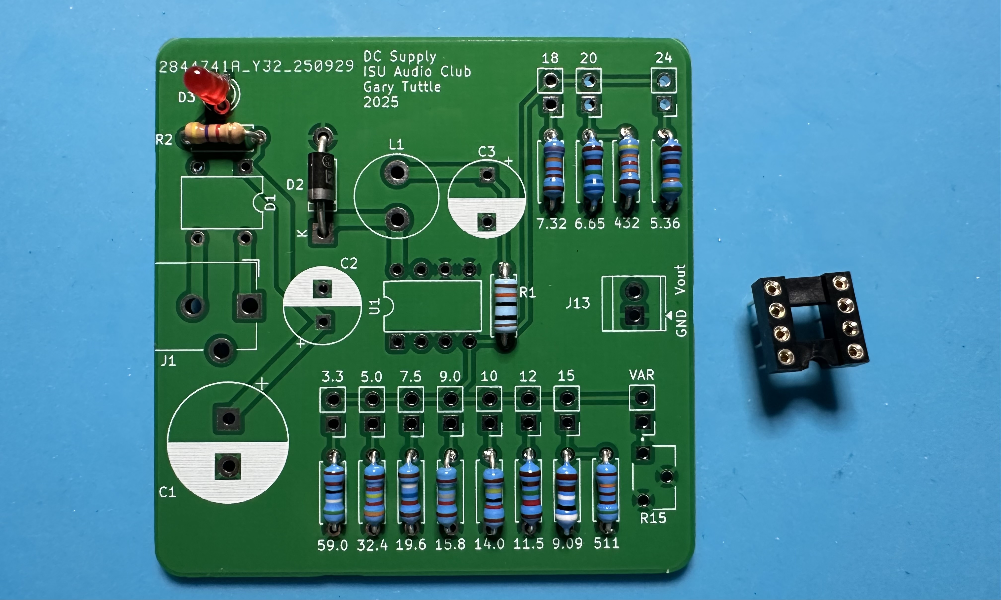
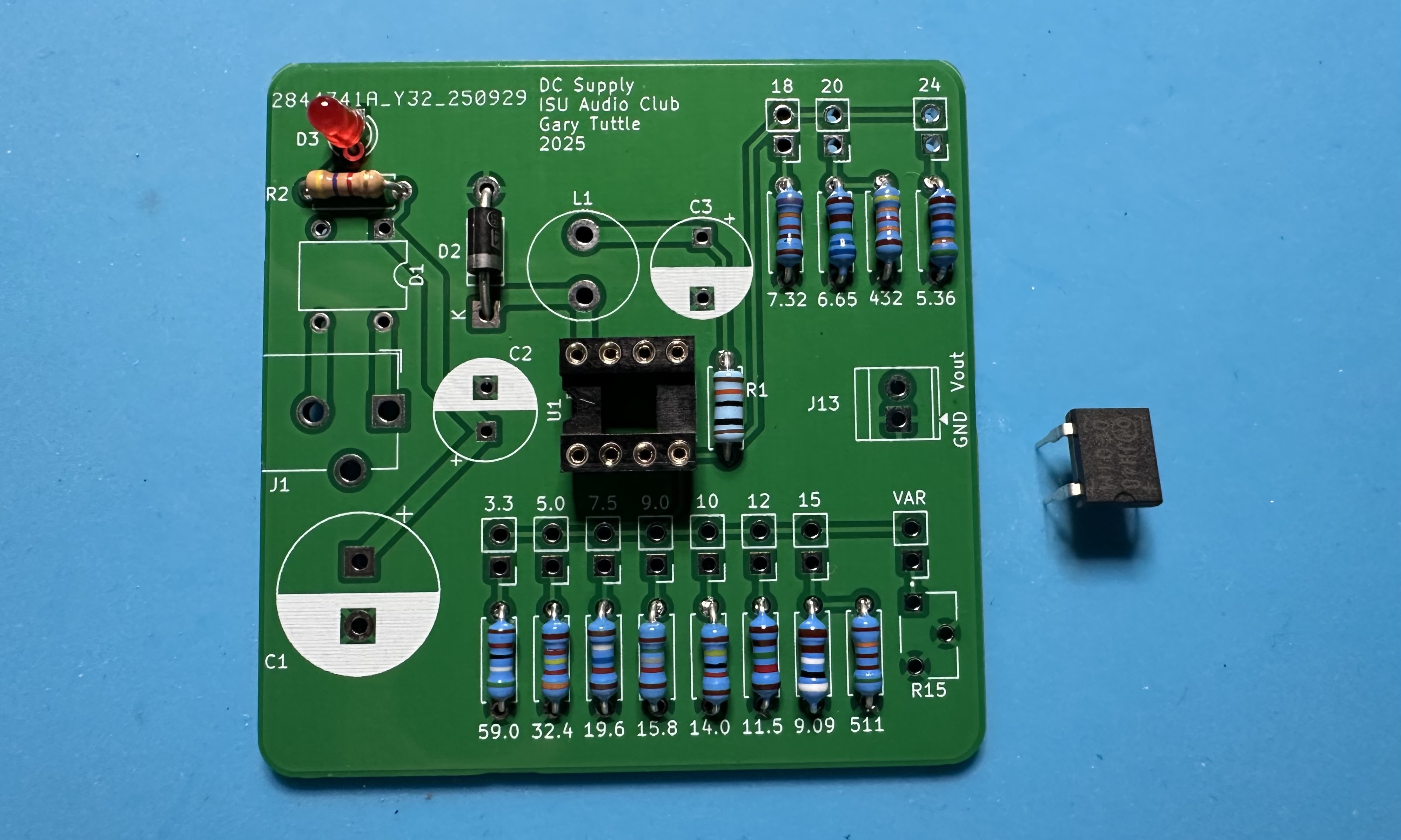
- We are ready for the 8-pin socket for the LM2594 chip. As always, solder one pin first, make any adjustments needed to ensure that the socket is seated properly, and then solder the rest of the pins.
- Now, the bridge rectifier for the AC input, labeled D1. Since it is a diode bridge, direction is important. Make sure the "notches" on the chip and the footprint match. (The little sine waves on the chip package should be next to the barrel-jack footprint, J1.)
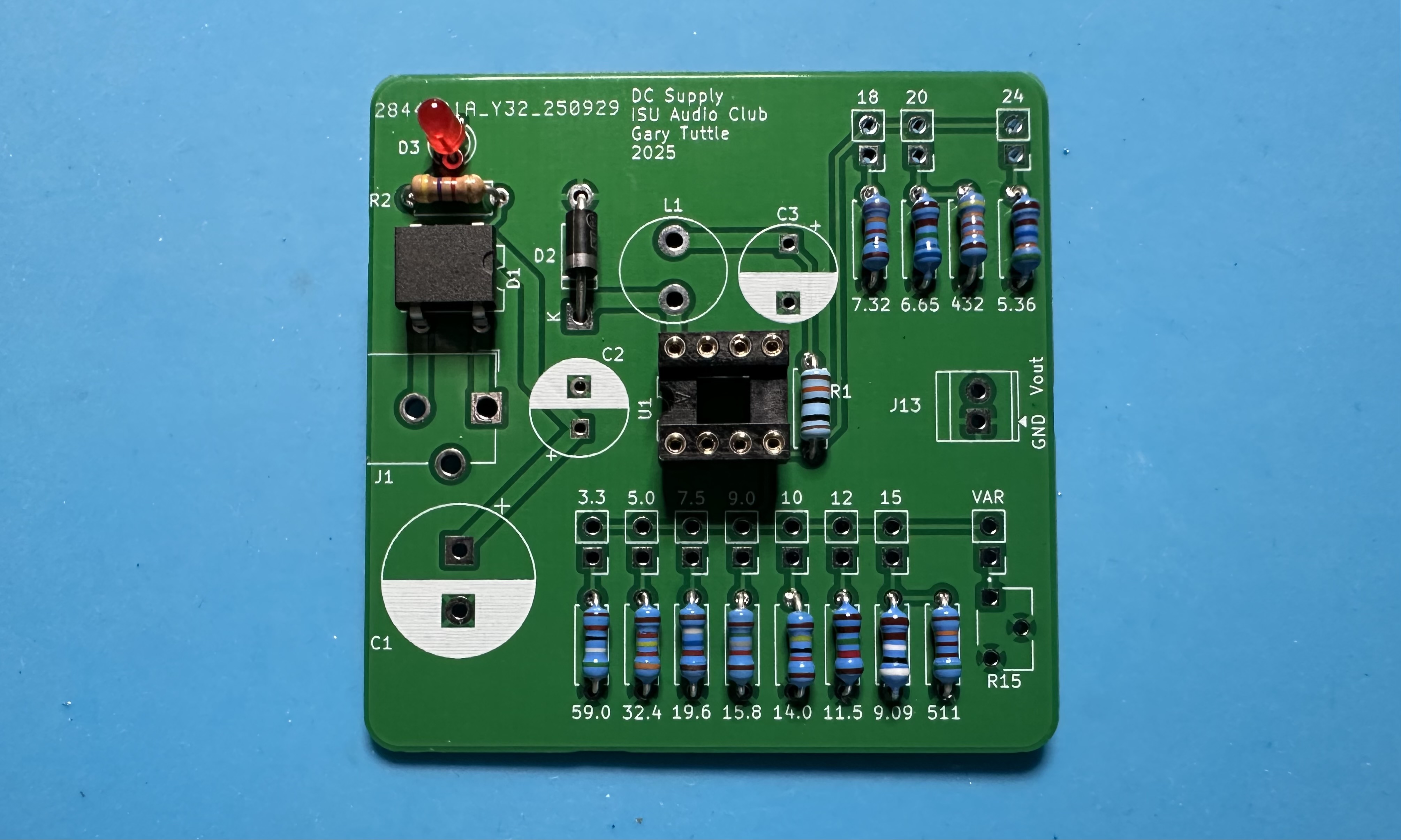
- We've come to the worst (most tedious) part — installing the 11 header-pin pairs that allow for selecting different output voltages. The pins come in a single 24-pin strip. Use needle-nosed pliers to break off a pair of pins and solder it into place next to one of the feedback resistors. Each header pair location on the PCB is labeled with one of the possible output voltages. Soldering these is a little bit tricky, as it is easy to have the pins leaning in one direction or the other. It is not a crime if the pins aren't vertical, but it may then be more difficult to slide the jumper in place. And it looks janky. Again, solder one side in place, make adjustments if needed, and then solder the other side. Repeat the process for the other 10 headers. At the end, you should have a couple of pins left over. If you mess up when breaking off a pair of pins from the strip, just move on to the next ones. If you end up needing more pins, GT or the IEEE folks will have some spares.)
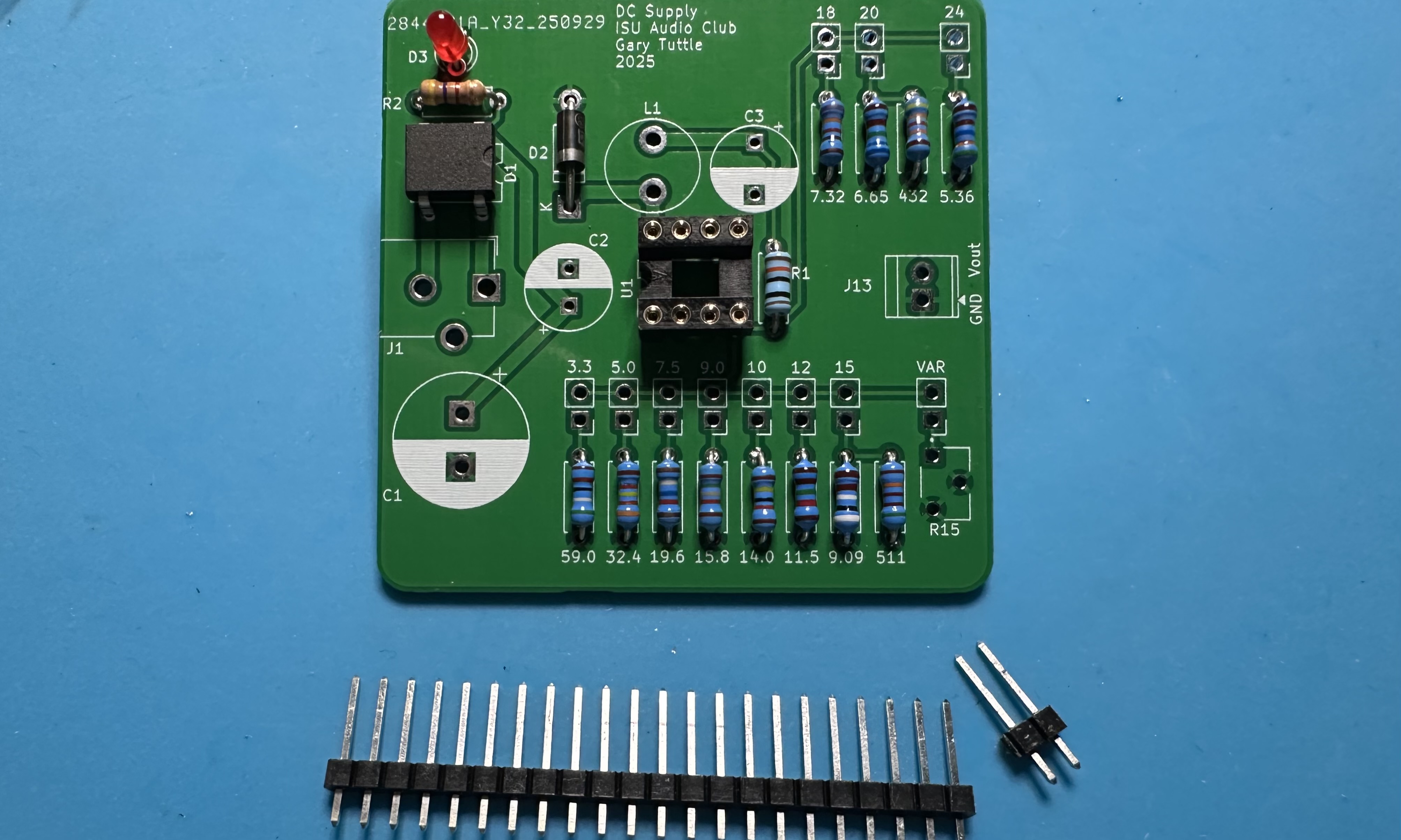
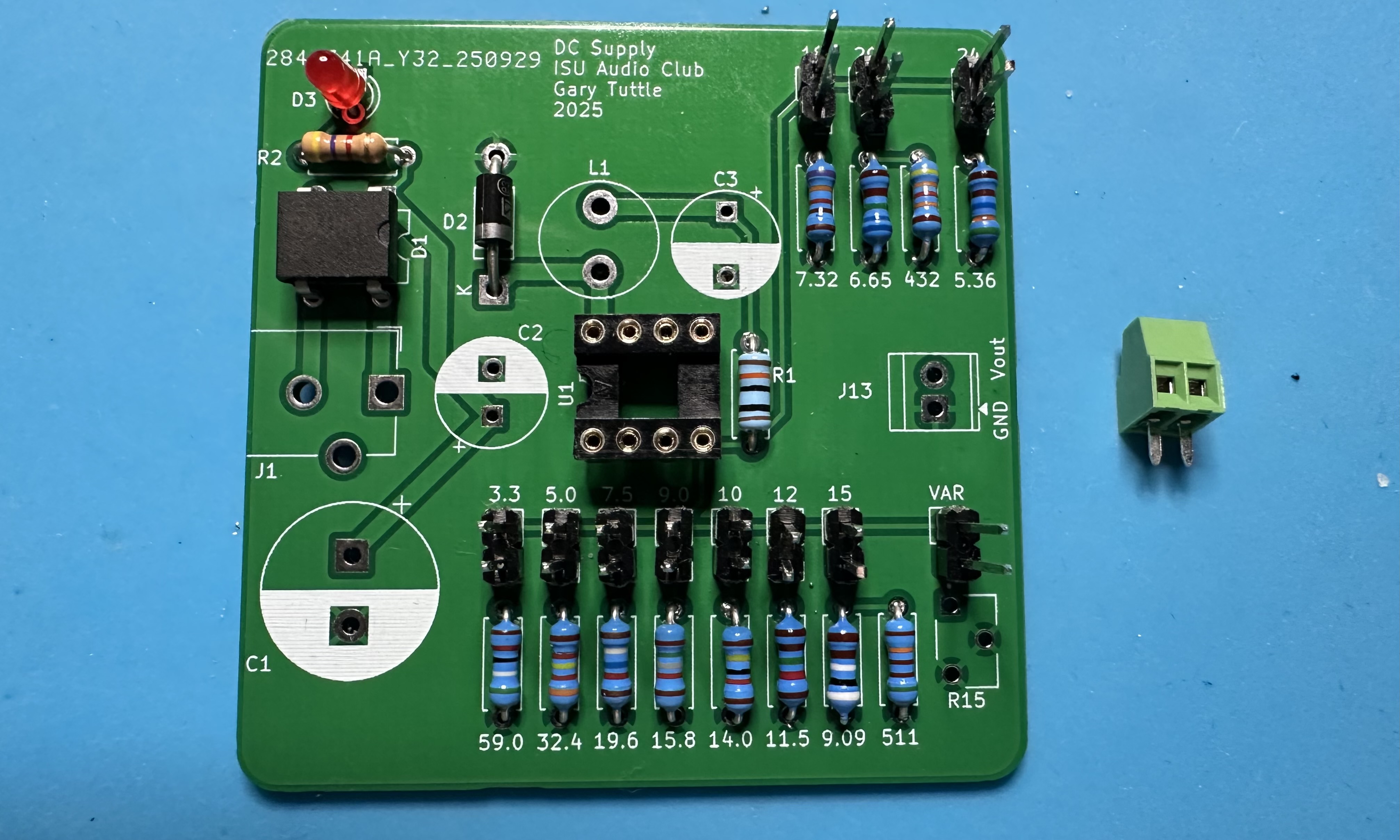
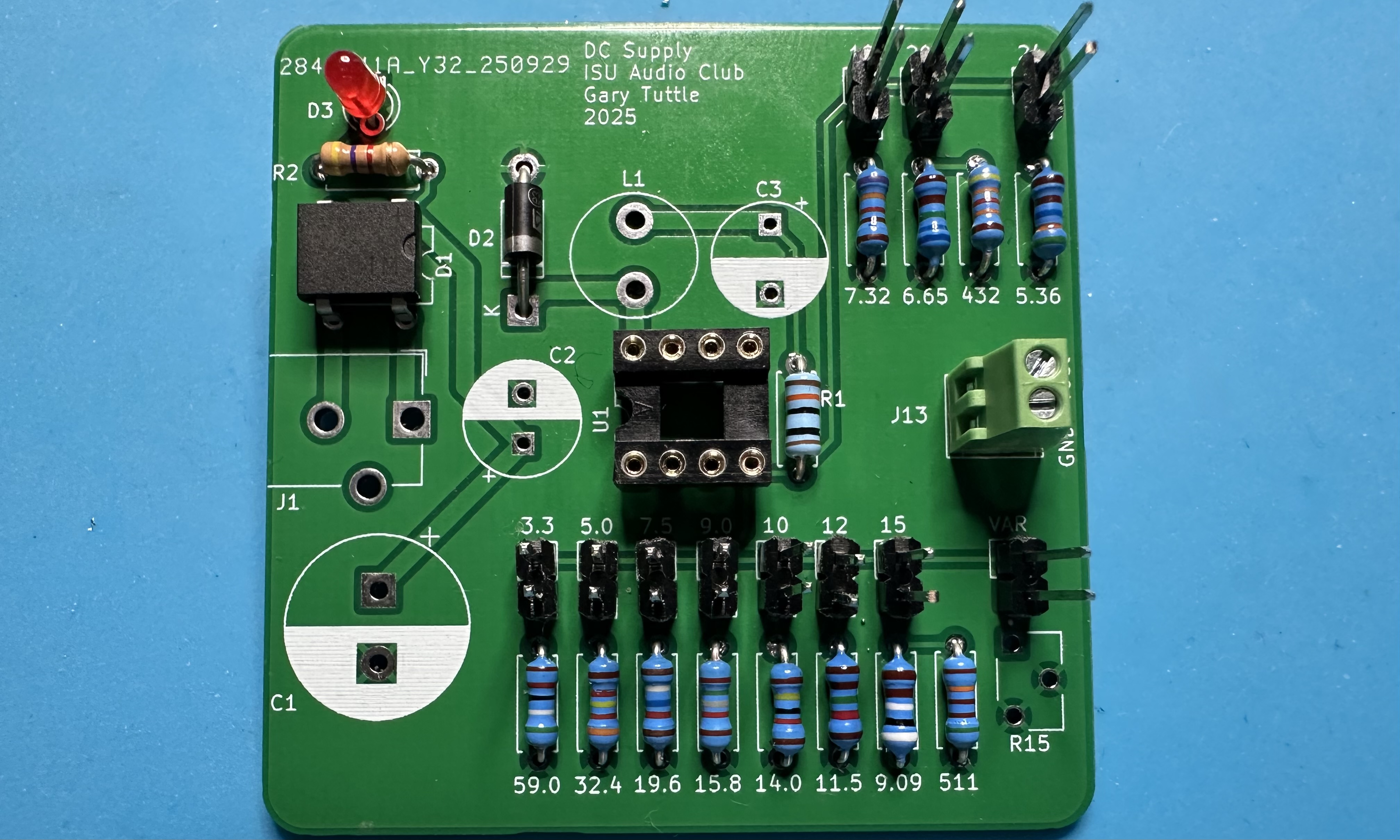
- After soldering all of those header pins, take a break — you deserve it. Then solder in the 2-position terminal for the output.
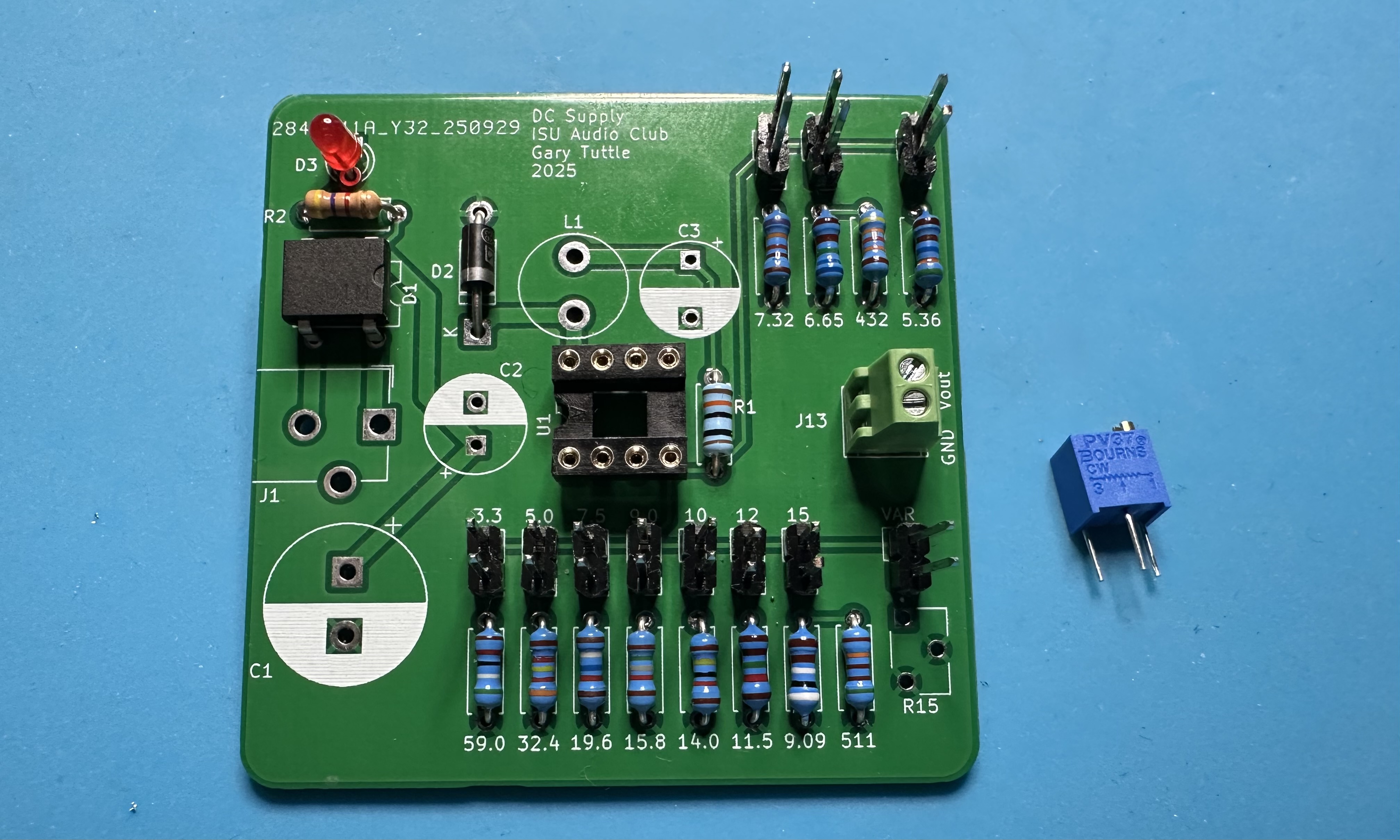
- Next, solder in the 12-turn potentiometer that allows for fine-tuned output voltages.
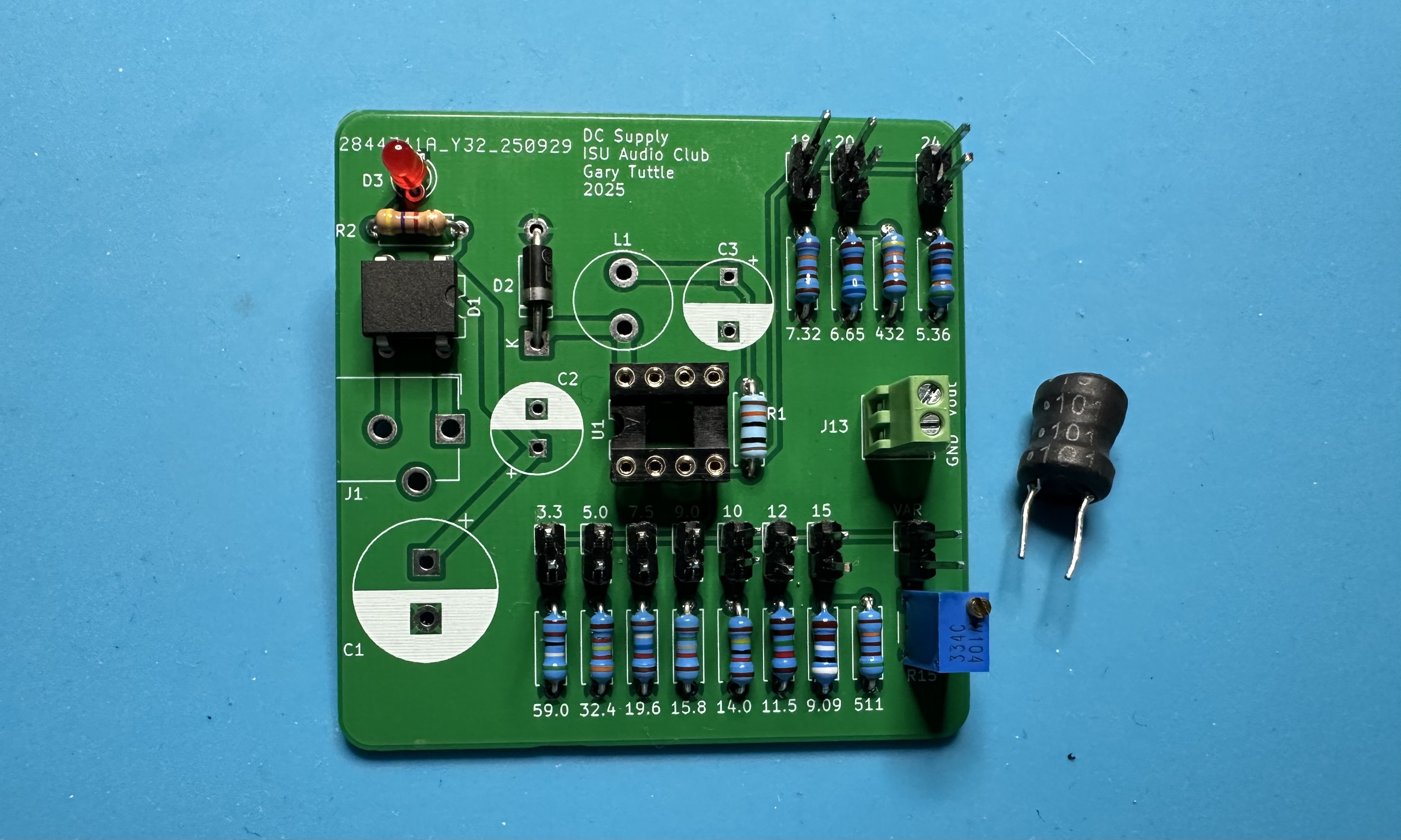
- Now add the 100-μH inductor, L1 on the board, for the switching regulator. It can go in either way.
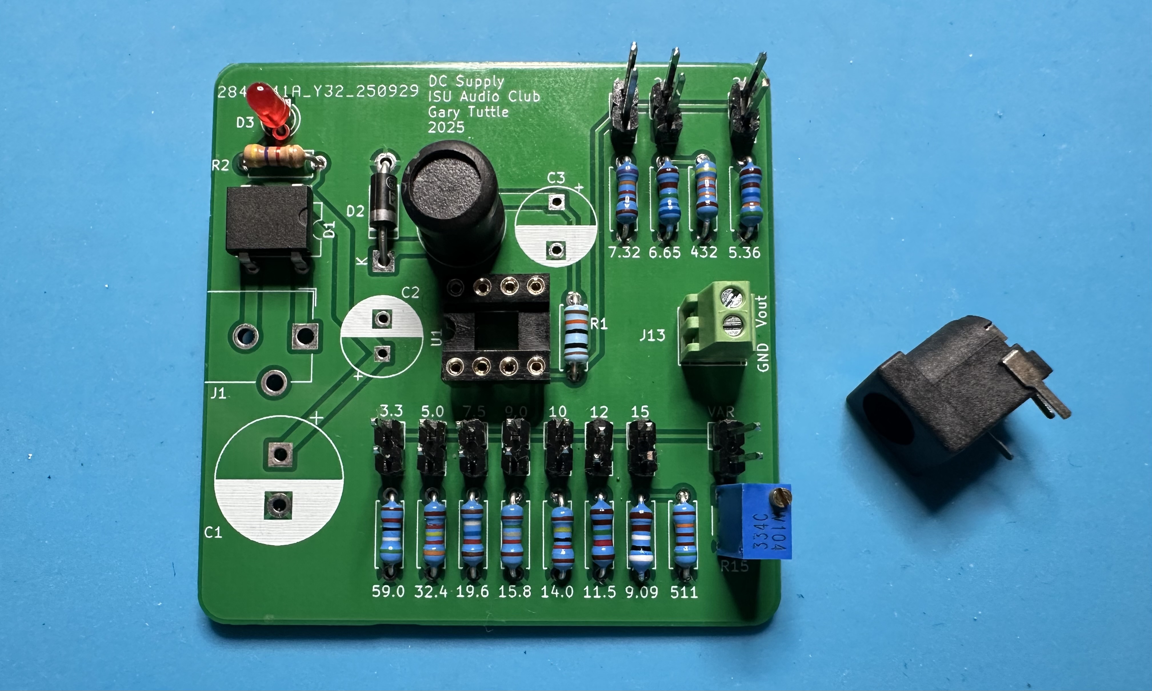
- Solder in the barrel-jack input.

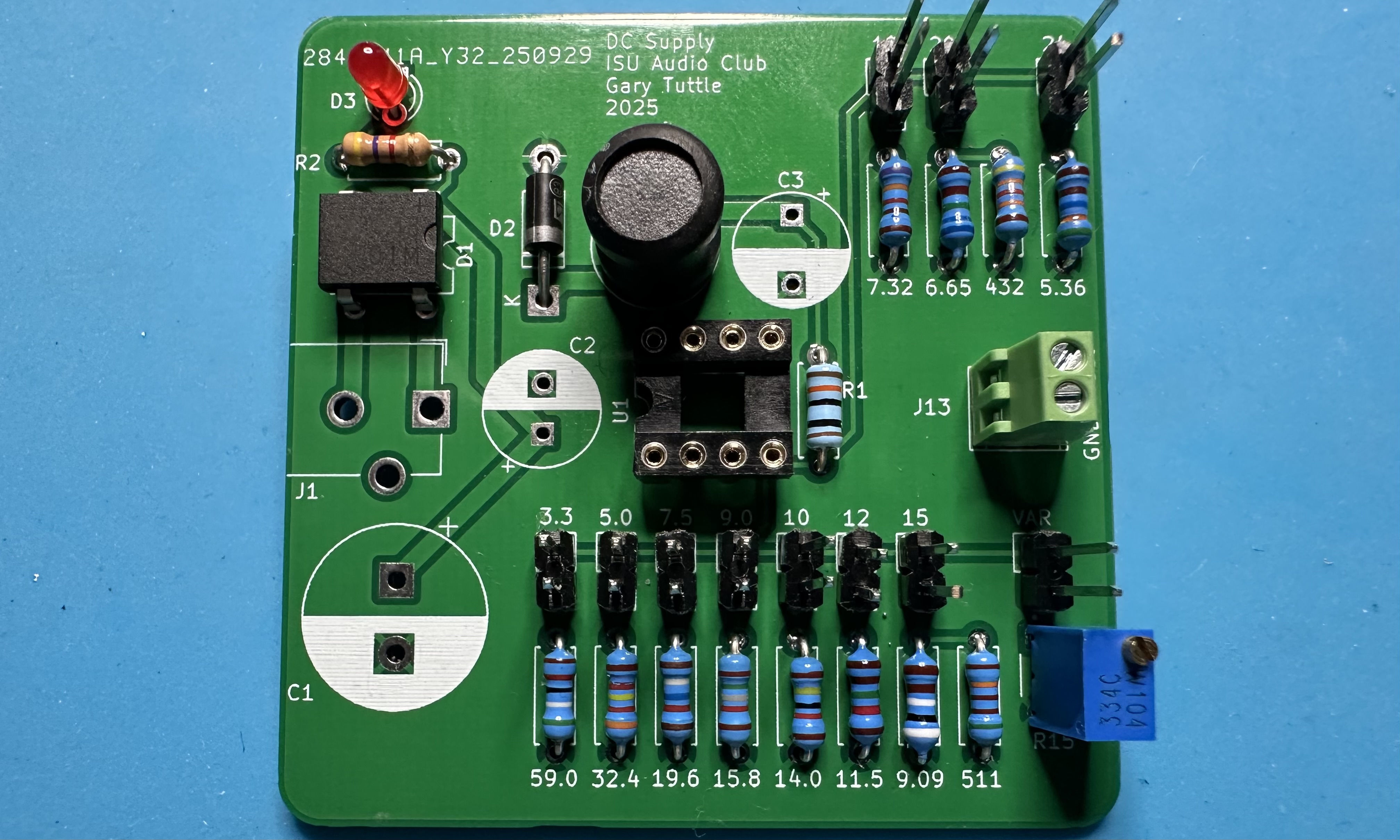
- The end is in sight! For the final bit of soldering, install the three capacitors: C1 (1000 µF), C2 (68 µF), and C3 (120 µF). These are electrolytic, so be sure to get them in the right way.
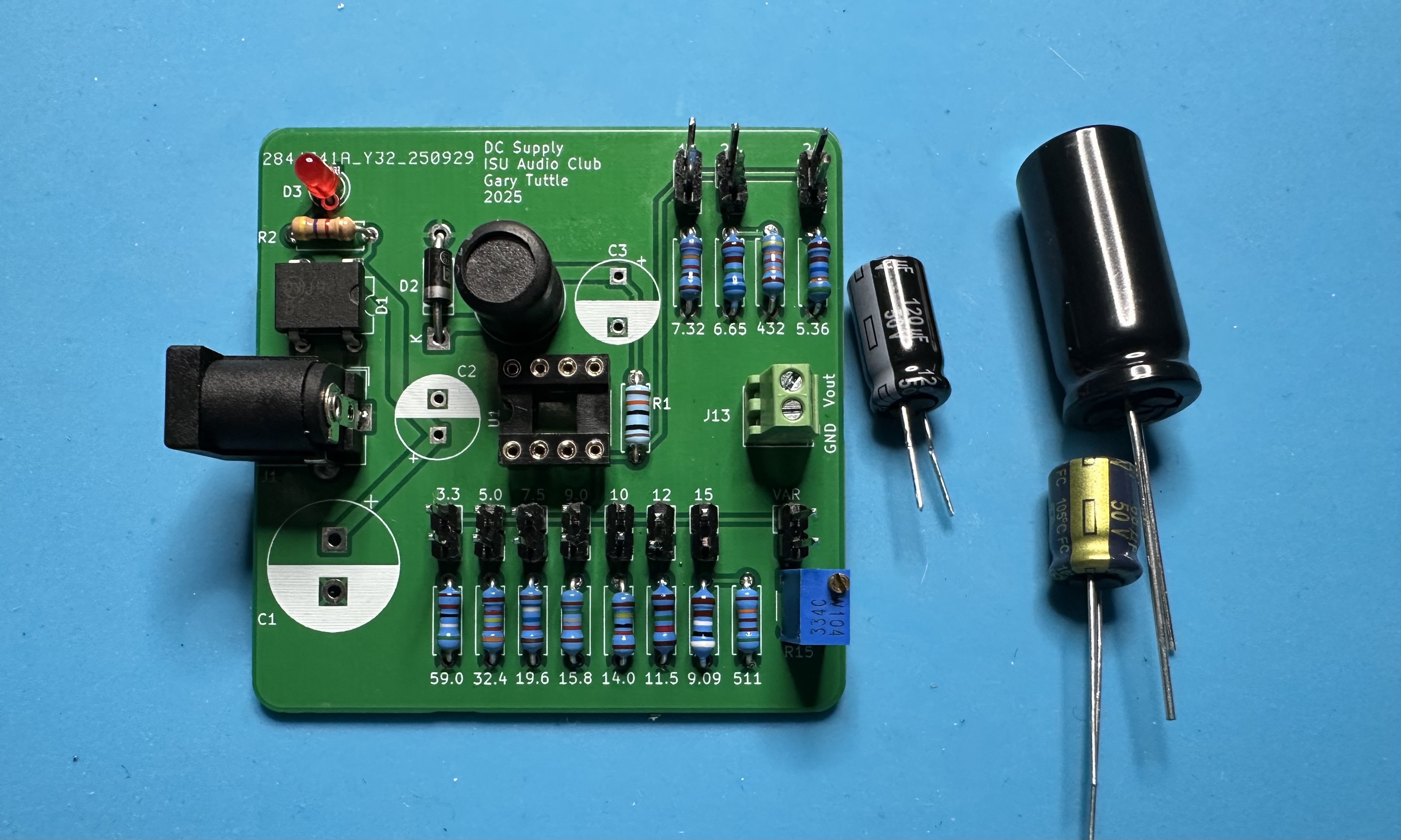
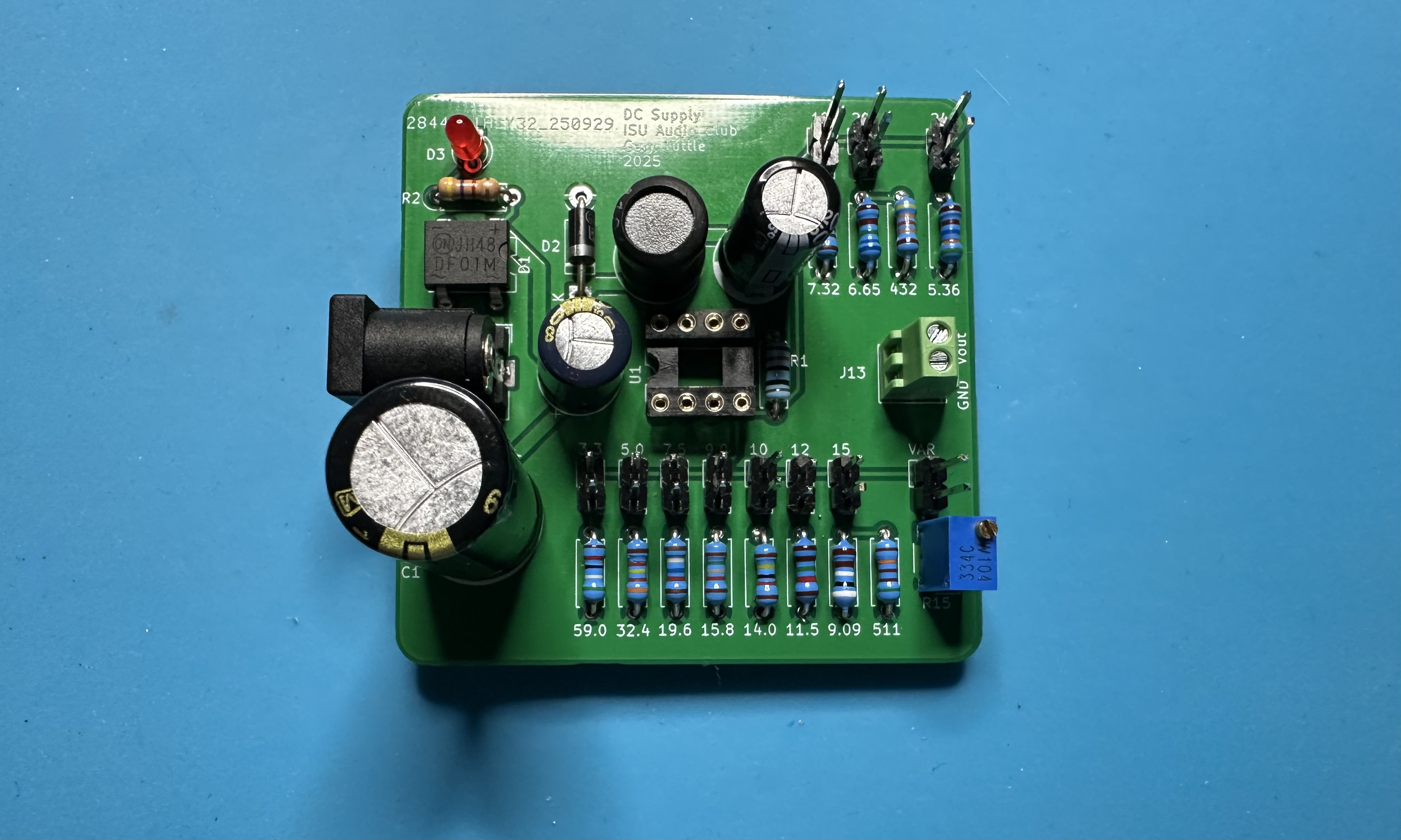
- To finish up, insert the LM2594 chip into the socket. As is typical, you may need to bend the pins inward a bit in order to get the chip to slide into the socket. Push the output voltage jumper onto a pair of header pins, and attach the "pig tail" to the output connector. YOu are ready to supply power to something!